Hacking the BR6101 broadband router
In February 2007 I bought a second hand broadband router: the Sweex LB100010, also known as BR6101 (the original Edimax name). It has a 4-port switch, a WAN port and a parallel printer port. At some point during figuring out how to use the printer with CUPS, I opened the case and found some space on the PCB for something like a DB9 connector. Serial? Yes, as it appears, since it was wired to the Conexant CX84200 SoC's serial port lines. Time for some investigation!
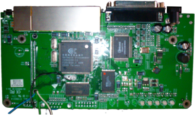
First some main components:
- Conexant CX84200 SoC, aka ADM5106,
- Winbond W83877TF I/O chip for the parallel port,
- 4MB of SDRAM (Winbond W987432DH-6),
- 1MB of flash memory (29LV8000ABTC-70).
This device is close kin to the BR6104, which has USB instead of parallel wired on the PCB. Most of these devices run Linux already. The ADM5106 however seems to be slightly different from the ADM5120, running Linux may not be that easy :( [1].
Connecting the serial port
The SoC's UART0 appears to be used as serial console. This is wired to the empty ic-spot at the back of the PBC, near the empty DB9 space on top. It's best to add wires at this place, since soldering the SoC itself can be dangerous, as I've personally experienced.
	     <to DB9-like connector>

	 14                           1
	   | | | | | | | | | | | | | |
	  +---------------------------+           pin 15 - Vss
	  |                          o|           pin 18 - UDI1 (SoC #157)
	  |                           |           pin 22 - UDI0 (SoC #154)
	  |                           |           pin 23 - UDO1 (SoC #158)
	  +---------------------------+           pin 25 - UDO0 (SoC #155)
	   | | | | | | | | | | | | | |
	 15|     |       | |   |      28

	   V     U       U U   U
	   s     D       D D   D
	   s     I       I O   O
		 1       0 1   0
So you need to solder a wire to pin 22 and 25, and find a suitable ground pin (I used the ground plate of a not connected oscillator as you may be able to see in the photo). These three wires (UDI0, UDO0 and GND) need to be connected to a 3V3 serial port. This has already been explained at various other places.
The bootloader
The bootloader interface is self-explanatory, but for once thing: the hidden commands. Enter ! (exclamation mark) at the [LBR Boot] prompt to enter the administrator mode. This adds two commands: G, to run code from a specific location, and R, for reading data from flash memory. It is possible to get a firmware dump with this, for example with this script. This would enable me to mess around with Linux and still go back to the original state, if I would be able to upload it again (not attempted yet!).
The bootloader has a command to display the memory areas. For this device, it gives:
      --------------------------------------
      Area         Address     Length
      --------------------------------------
      [0] Boot          0x00000000     128K
      [1] Configuration 0x00020000      64K
      [2] Web Image     0x00030000     192K
      [3] Code Image    0x00060000     576K
      [4] Params Area   0x000F0000      64K
      --------------------------------------
This bootloader has been found in other devices too and people have been able to load Linux with it: Siemens SX541, Sinus 154 DSL, SMC7004, NorthQ9100, and SMC7908VoWBRB.
When the original firmware is booted, these boot messages are shown.